
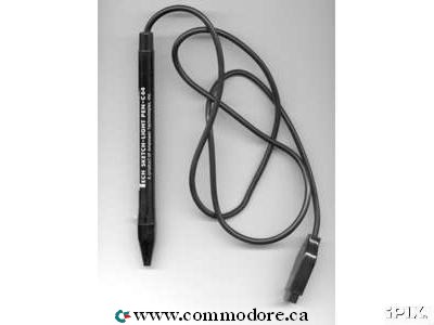
Pen plotters print by moving a pen across the surface of a piece of paper. This means that plotters are restricted to line art, rather than raster graphics as with other printers. Pen plotters can draw complex line art, including text, but do so very slowly because of the mechanical movement of the pens. Pen Plotters are incapable of creating a solid region of color; but can hatch an area by drawing a number of close, regular lines. When computer memory was very expensive, and processor power was very slow, this was often the fastest way to produce color high-resolution vector-based artwork, or very large drawings efficiently.
Traditionally, printers are primarily for printing text. This makes it fairly easy to control, simply sending the text to the printer is usually enough to generate a page of output. This is not the case of the line art on a plotter, where a number of printer control languages were created to send the more detailed commands like "lift pen from paper", "place pen on paper", or "draw a line from here to here". The two common ASCII-based plotter control languages are Hewlett-Packard's HPGL2 or Houston Instruments DMPL with commands such as "PA 3000, 2000; PD".
Programmers in FORTRAN or BASIC generally did not program these directly, but used software packages such as the Calcomp library, or device independent graphics packages such as Hewlett-Packard's AGL libraries or BASIC extensions or high end packages such as DISSPLA. These would establish scaling factors from world coordinates to device coordinates, and translating to the low level device commands. For example to plot X*X in HP 9830 BASIC, the program would be
**************************************
10 SCALE -1,1,1,1
20 FOR X =-1 to 1 STEP 0.1
30 PLOT X, X*X
40 NEXT X
50 PEN
60 END
**************************************
Early plotters (e.g. the Calcomp 565 of 1959) worked by placing the paper over a roller which moved the paper back and forth for X motion, while the pen moved back and forth on a single arm for Y motion. Another approach (e.g. Computervision's Interact I) involved attaching ball-point pens to drafting pantographs and driving the machines with motors controlled by the computer. This had the disadvantage of being somewhat slow to move, as well as requiring floor space equal to the size of the paper, but could double as a digitizer. A later change was the addition of an electrically controlled clamp to hold the pens, which allowed them to be changed and thus create multi-colored output.
Hewlett Packard and Tektronix created desk-sized flatbed plotters in the late 1970s. In the 1980s, the small and lightweight HP 7470 used an innovative "grit wheel" mechanism which moved only the paper. Modern desktop scanners use a somewhat similar arrangement. These smaller "home-use" plotters became popular for desktop business graphics, but their low speed meant they were not useful for general printing purposes, and another conventional printer would be required for those jobs. One category introduced by Hewlett Packard's MultiPlot for the HP 2647 was the "word chart" which used the plotter to draw large letters on a transparency. This was the forerunner of the modern Powerpoint chart. With the widespread availability of high-resolution inkjet and laser printers, inexpensive memory and computers fast enough to rasterize color images, pen plotters have all but disappeared.
Plotters were also used in the Create-A-Card kiosks that were available for a while in the greeting card area of supermarkets that used the HP 7475 6 pen plotter.
Plotters are used primarily in technical drawing and CAD applications, where they have the advantage of working on very large paper sizes while maintaining high resolution. Another use has been found by replacing the pen with a cutter, and in this form plotters can be found in many garment and sign shops.
If a plotter was commanded to use different colors it had to replace the pen and select the wanted color and/or width.
A niche application of plotters is in creating tactile images for visually handicapped people on special thermal cell paper.
Pen plotters have essentially become obsolete, and have been replaced by large-format inkjet printers and LED toner based printers. Such printers are often still known as plotters, even though they are raster devices rather than pen based plotters by the definition of this article. The newer plotters still understand vector languages such as HPGL2. This is because the language is an efficient way to describe how to draw the file using just text commands. A technical drawing in HPGL2 can be quite a bit smaller file than the same drawing in a pure raster form.
A pen plotter's speed is primarily limited by the type of pen used. The typical plotter pen uses a cellulose fiber rod inserted through a circular foam tube saturated with ink, with the end of the rod sharpened into a conical tip. As the pen moves across the paper surface, capillary wicking draws the ink from the foam, down the rod, and onto the paper. As the ink supply in the foam is depleted, the migration of ink to the tip begins to slow down, resulting in faint lines. Slowing the plotting speed will allow the lines drawn by a worn-out pen to remain dark, but the fading will continue until the foam is completely depleted. Also as the fiber tip pen is used, the fiber tip slowly wears away from rubbing against the media, wearing down the thin conical tip into a thicker smudged line.
Ball-point plotter pens with refillable clear plastic ink reservoirs are available. They do not have the fading or wear effects of fiber pens, but are generally more expensive and uncommon.


![[IBM 701 punched card]](http://www.cs.uiowa.edu/%7Ejones/cards/collection/ibm701.gif)
![[bell labs punched card]](http://www.cs.uiowa.edu/%7Ejones/cards/collection/bell1.gif)
![[generic FORTRAN punched card]](http://www.cs.uiowa.edu/%7Ejones/cards/collection/fortran.gif)
![[University of Illinois generic punched card]](http://www.cs.uiowa.edu/%7Ejones/cards/collection/illinois.gif)
![[Princeton University punched card]](http://www.cs.uiowa.edu/%7Ejones/cards/collection/princeton.gif)
![[MIT punched card]](http://www.cs.uiowa.edu/%7Ejones/cards/collection/mit.gif)
![[IBM 96-col punched card]](http://www.cs.uiowa.edu/%7Ejones/cards/collection/ibm96col.gif)
![[string of Jacquard cards]](http://www.cs.uiowa.edu/%7Ejones/cards/collection/jaquard.gif)
![[round hole sperry punched card]](http://www.cs.uiowa.edu/%7Ejones/cards/collection/sperryce.gif)
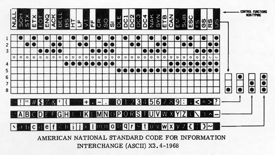
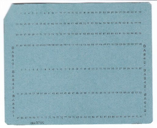
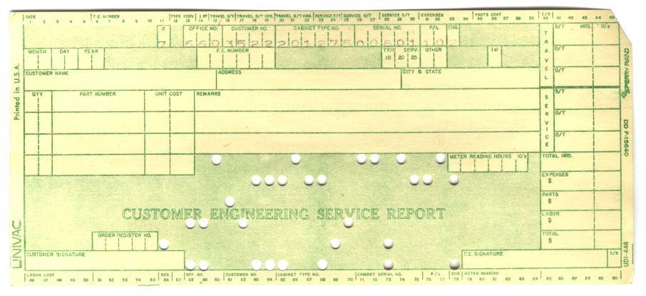
![[punched card retail form]](http://www.cs.uiowa.edu/%7Ejones/cards/collection/retail.gif)
![[Gardner-Denver wire-wrap punched card]](http://www.cs.uiowa.edu/%7Ejones/cards/collection/gardner.gif)
